Rebecca Moretta
Portfolio  ·  Mechanical Engineering

Rebecca
MorettaMechanical Engineer

Design  ·  Robotics  ·  Simulation

Discover
Portrait of Rebecca Moretta
Rebecca Moretta
N° 01 — About

An early start, and a steady pursuit of precision — from CAD to code to the physics in between.

I left high school at sixteen and earned my GED so I could begin my undergraduate degree in mechanical engineering early. Since then, I've worked to sharpen my skills in CAD, programming, and electromechanical design.

I design in SolidWorks, Onshape, CATIA, and Siemens NX, and program in C, C++, Python, and MATLAB. I have experience with ROS2 and with training object detection models, and I've recently been diving deeper into FEA and CFD so I can apply them with confidence.

EducationFlorida Polytechnic University
B.S. Mechanical Engineering
N° 02

Expertise

Tools of the craft

I

Mechanical CAD

  • SolidWorks
  • Onshape
  • CATIA
  • Siemens NX
II

Programming

  • C
  • C++
  • Python
  • MATLAB
III

Simulation

  • Ansys
  • COMSOL Multiphysics
  • SolidWorks Simulation
  • FEA & CFD
IV

Robotics

  • ROS2
  • Object Detection
  • PID Control
  • Sensor Integration
N° 03

Selected Work

Three projects

Capstone Robotic Arm

Group Capstone
Mechanical & Electrical Lead
Objective

Design an attachment for a rover that would facilitate construction on the lunar surface.

SolidWorksMATLAB3D PrintingElectronics
Process

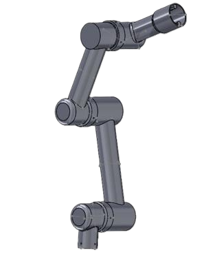
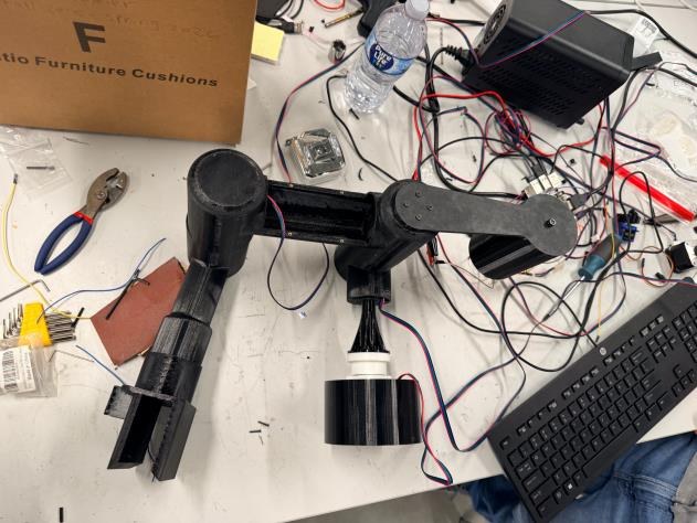
In this group project I was in charge of the mechanical design and assembly, as well as electrical design and sensor integration. I chose a robotic arm for its versatility and familiarity, modelling the design after palletizing arms used in industrial applications.

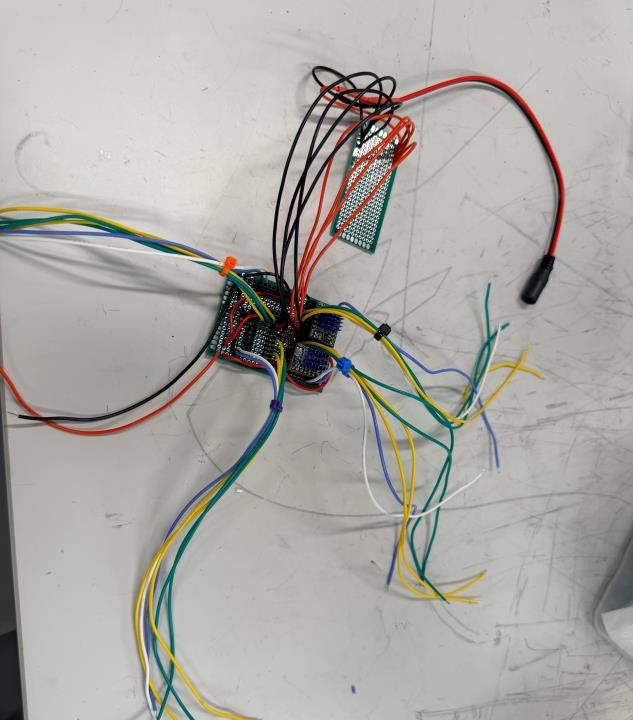
We began by outlining what the arm needed to accomplish, and I iterated several designs in SolidWorks. Once we settled on a final design, we simulated the arm's kinematics in MATLAB. For the electronics, I prototyped on a breadboard, then moved the finalized circuit to a perforated board for a clean build with no loose wires — choosing it over a manufactured PCB so shipping time wouldn't eat into testing.

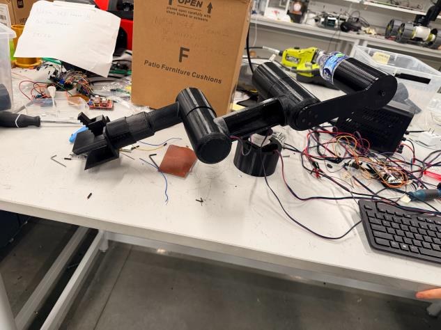
During testing, the PETG gearboxes kept skipping due to the material's low rigidity. Reprinting them in PLA solved the problem, and I added a counterweight to help the arm carry its own weight.
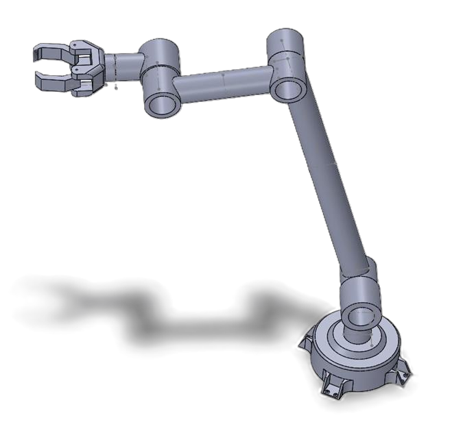
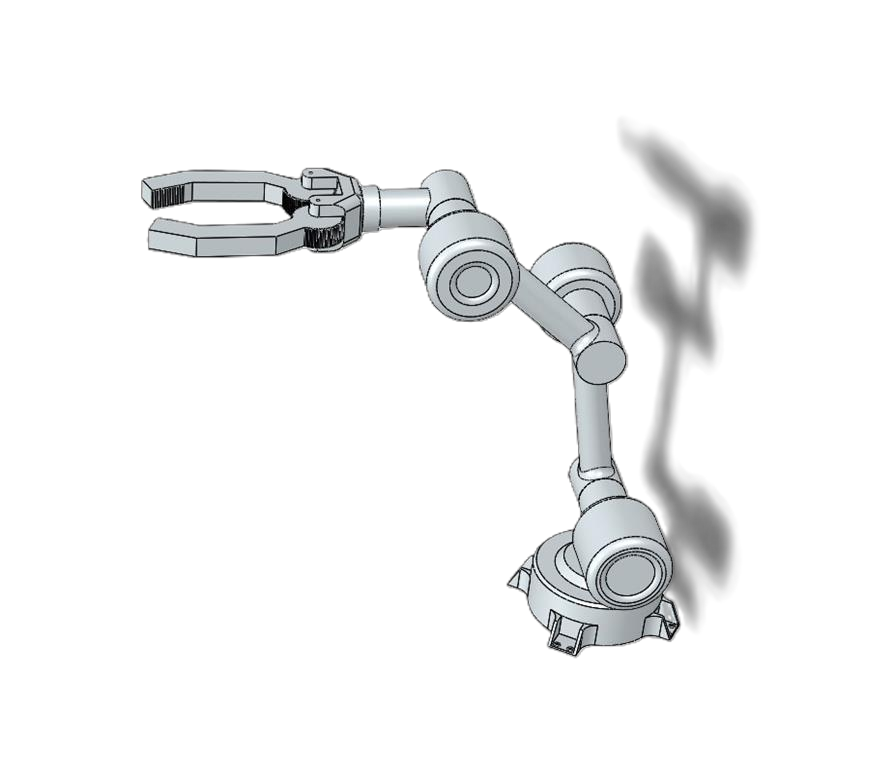
Robotic arm CAD, extended with gripper
Arm assembly — reach
Robotic arm CAD, compact pose
Arm assembly — iteration
Robotic arm CAD, final design
Final arm design
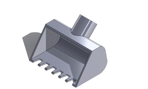
Excavation bucket end effector CAD
Bucket end effector
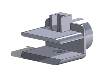
Gripper mount CAD
Tool mount
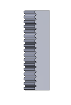
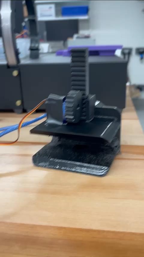
Gear rack CAD
Gear rack
3D printed gearbox and servo on bench
Printed gearbox
Assembled robotic arm on the lab bench
Assembled arm
Robotic arm during testing
Testing
Perforated circuit board wiring
Perf-board circuit

Autonomous Robot

Computer Vision
Controls
Objective

Train an object detection model and deploy it on a small robot that completes three laps of a track, stops at red lines, and yields for rubber-duck “pedestrians” — a miniature self-driving car.

PythonObject DetectionPIDPETG
Process

I began by training an object detection model on about 40 images of white lines, yellow lines, red lines, and rubber ducks.

I then assembled the robot on a 3D-printed PETG base with four DC motors, four wheels, a Radxa Rock 5C board, a 12V battery, two DC motor drivers, and a PID board. After mapping each motor to the keyboard, I wrote a Python script that follows the midpoint between the lane lines using the detection model, then tuned the PID controls to improve the accuracy and speed of the robot's movement.

40Training images
3Laps, autonomous
4DC motors · PID tuned
I — Live object detection
II — Lane following
III — On the track

Heat Sink Research

Thermal Simulation
SolidWorks
Objective

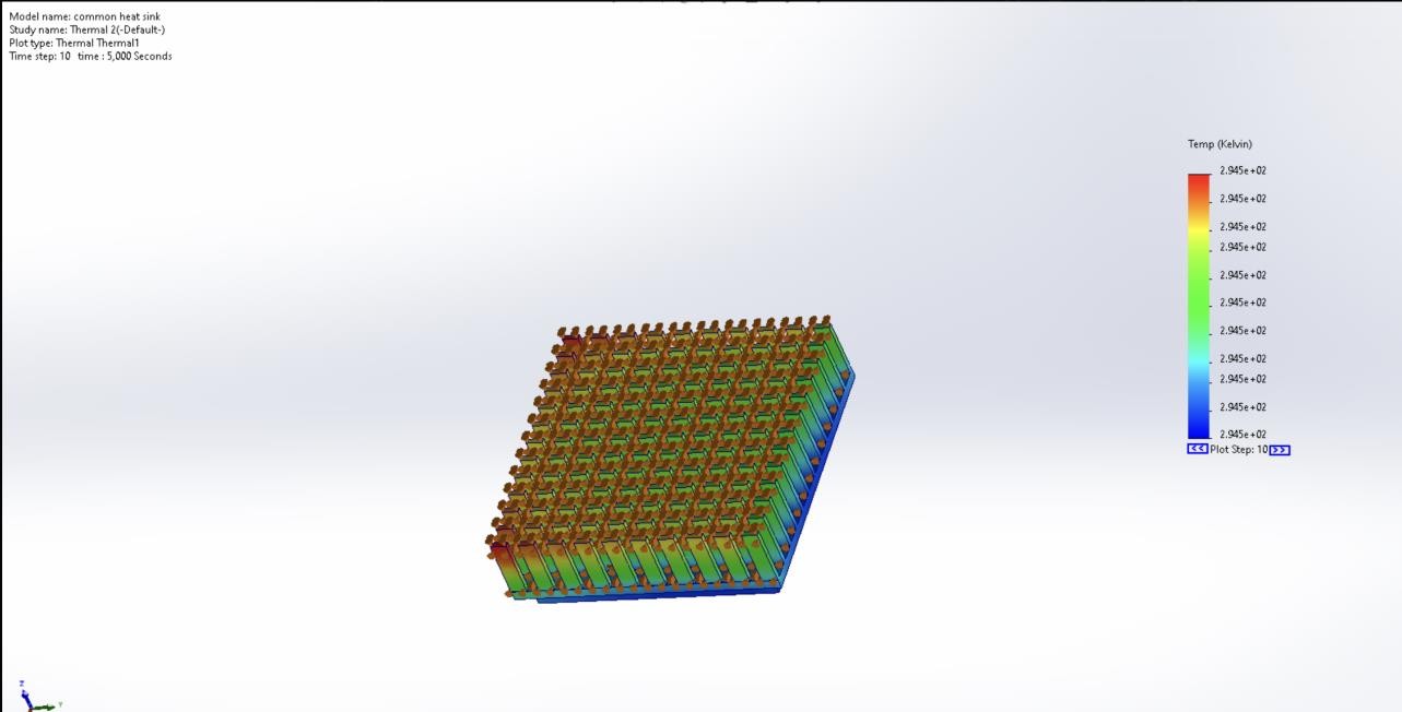
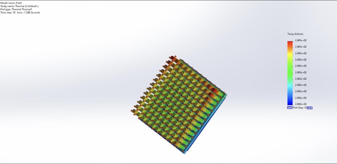
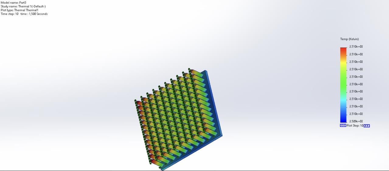
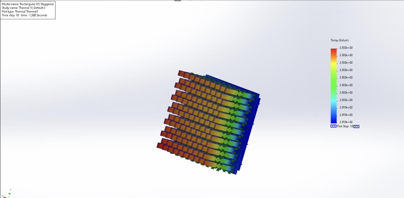
Design a family of heat sinks and discover which changes improve heat dissipation under constant forced convection — varying fin shape, length, and arrangement.

SolidWorks SimulationHeat TransferConvection
Process

I began by designing a control heat sink with rectangular fins in an in-line array, then a second with the same fin shape and length in a staggered array. From there I continued designing heat sinks with varying fin cross-sectional geometry and fin lengths.

Every design was run through a SolidWorks thermal simulation with an applied convection, and the results were compared side by side.

Thermal simulation of control heat sink
I — Control, in-line rectangular fins
Thermal simulation of heat sink variant
II — Fin geometry variant
Thermal simulation of heat sink variant
III — Fin geometry variant
Thermal simulation of staggered heat sink
IV — Staggered array
Finding Fin shape made mostly negligible difference — fin arrangement and length improved heat dissipation greatly.
N° 04

Coursework

Mechanical design

I

Design & Analysis of Machine Components

II

Engineering Failure Analysis

III

Introduction to Vibrations & Controls